


Communication Protocols: The Backbone of Industrial Connectivity
Navigating the world of industrial automation can often feel like navigating an alphabet soup of technologies. At the heart of these systems are two fundamental elements: communication protocols, which define the language being spoken, and physical layers, which provide the medium through which that language travels.
In industrial communication, the physical layer, or Layer 1, comprises the actual hardware, including wires, connectors and electrical signals that carry data. Protocols such as Modbus or BACnet define the language, while the physical layer provides the means to carry it.
A simple analogy is a postal system. The physical layer is the road, truck and envelope, while the protocol determines the language and formatting of the letter inside. Both need to work together. The devices may speak the same language, but without a functioning physical connection, communication cannot take place. Similarly, a reliable physical connection is of little use if the devices do not understand the same protocol.
1. Communication Protocols
A protocol is a set of rules governing how data is packaged, addressed and sent. It ensures that the device receiving the information can reassemble the transmitted bits into meaningful data.
A protocol comprises:
- Framing: Defines where a message starts and ends.
- Addressing: Identifies who is sending the message and who is intended to receive it.
- Error checking: Uses mechanisms such as a checksum or Cyclic Redundancy Check (CRC) to determine whether data was corrupted during transmission.
- Data structure: Defines how information is organised within the message. For example, the first two bytes may represent temperature and the next two pressure.
Some of the most commonly used protocols in industrial and building automation include Modbus, PROFIBUS, PROFINET, BACnet, TCP/IP, DeviceNet, OPC and CAN Bus.
Modbus
Modbus is a request-response protocol based on a master/slave, or client/server, architecture. The protocol defines how a device requests data, identifies itself and reports errors.
Whether RTU or TCP is used, the data unit remains largely the same, with devices requesting to read or write specific registers or data-storage points.
1. Modbus RTU
Modbus RTU, or Remote Terminal Unit, is the traditional serial version of Modbus. It is commonly used over RS-485 or RS-232 physical connections, with data transmitted as a continuous stream of binary characters.
It uses CRC for error checking, providing a mathematical checksum at the end of the packet to identify whether bits have changed during transmission.
Typical baud rates range from 9.6 kbps to 115.2 kbps, and devices are generally connected in a daisy-chain configuration. RS-485 can support distances of up to 1,200 metres, making Modbus RTU suitable for legacy equipment, long-distance communication with simple wiring and low-cost sensor applications.
2. Modbus TCP
Modbus TCP, or Transmission Control Protocol, is designed to operate over Ethernet networks. The Modbus data is wrapped inside a TCP/IP packet.
Because Ethernet handles delivery and addressing, some parts of the original RTU message, such as the Slave ID and CRC, may be modified or removed. Instead, the standard TCP/IP checksum is used for data integrity.
Modbus TCP operates at 10/100/1000 Mbps and uses standard CAT5/CAT6 cables and network switches. Ethernet also enables more complex star topologies rather than simple daisy chains.
Modbus TCP is suited to applications with existing IT infrastructure, requirements for high-speed data transfer or the need to connect multiple clients to the same device.
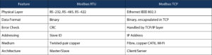
Table 1: Comparison of Modbus Protocols
PROFIBUS
PROFIBUS, or Process Field Bus, is a widely used fieldbus protocol in industrial automation. It connects sensors, actuators and controllers on the factory floor.
1. PROFIBUS DP
PROFIBUS DP, or Decentralised Periphery, was designed to replace conventional 4–20 mA analogue signals by enabling a PLC to communicate with multiple field devices, including sensors and drives, over a single cable.
It uses RS-485 twisted-pair copper, with speeds of up to 12 Mbps. Devices are typically arranged in a daisy chain. PROFIBUS DP is commonly used for factory automation and high-speed communication between controllers and I/O.
2. PROFIBUS PA
PROFIBUS PA, or Process Automation, was developed specifically for process industries, including oil and gas and chemical facilities where environmental safety is an important consideration.
It uses the Manchester Bus Powered (MBP) standard and is designed for hazardous areas. Electrical energy is limited to help prevent a spark that could cause ignition. The same two wires carry both data and power to the instruments.
PROFIBUS PA operates at a fixed speed of 31.25 kbps.
3. PROFINET
PROFINET is the modern evolution of PROFIBUS. While PROFIBUS is based on serial communication, PROFINET uses Industrial Ethernet.
Standard Ethernet CAT5/CAT6 cables or fibre-optic cables can be used for communication, with speeds ranging from 100 Mbps to 1 Gbps.
Because it is Ethernet-based, PROFINET supports star, tree and ring topologies using standard network switches. It can also coexist with standard office traffic, web servers and wireless technologies such as WLAN and Bluetooth.

Table 2: Comparison of PROFIBUS Protocols
BACnet
BACnet, or Building Automation and Control Networks, was designed specifically for smart buildings. It defines not only how data is transmitted, but also what the data represents, such as temperature or schedules.
BACnet uses an object-oriented approach. Instead of searching for a particular memory address, a system can request a defined object, such as an analogue input.
The protocol enables interoperability between different brands of HVAC and fire systems and natively supports functions including scheduling, alarming and trending. It is suited to applications in commercial buildings, hospitals and campuses.
TCP/IP
The TCP/IP, or Transmission Control Protocol/Internet Protocol, suite provides a framework that allows computers to communicate over a network. Combined with Ethernet, it forms the foundation of modern local area networks and the internet.
TCP/IP can be understood through a four-layer model, with data packaged at each stage.
1. Network Access Layer: Ethernet
This is where the physical connection occurs. Ethernet handles cables, switches and network cards and uses MAC addresses as unique hardware identifiers. At this level, data is referred to as a frame.
2. Internet Layer: IP
The Internet Layer is responsible for routing data across different networks using Internet Protocol. It determines the path for a packet to travel from sender to receiver.
3. Transport Layer: TCP
The Transport Layer manages connections between applications using Transmission Control Protocol.
TCP provides reliability by breaking large amounts of data into numbered segments. If a segment is lost, TCP requests that it be transmitted again.
4. Application Layer
The Application Layer is where users interact with network-enabled applications. Examples include HTTP for web browsing, SMTP for email and FTP for file transfers.
DeviceNet
DeviceNet is a digital, multi-drop communication protocol used in industrial automation to connect controllers such as PLCs with input/output devices, including sensors, motor starters and pushbuttons.
Originally introduced in 1994, DeviceNet is based on Controller Area Network technology. It uses the physical and data-link layers of CAN while adding an upper-layer protocol known as the Common Industrial Protocol (CIP).
Open Platform Communications
OPC, or Open Platform Communications, is a software interface standard that allows hardware from different manufacturers to communicate with a central PC or cloud system.
It is used in large-scale factory integration where data from several different types of machines needs to be brought into a common dashboard or system.
CAN Bus
Originally designed for the automotive industry, Controller Area Network is a robust communication protocol capable of automatically handling message collisions.
CAN provides strong error detection, retransmitting a message when communication fails. It also uses priority-based messaging so that important data can be transmitted first.
Communication distance varies with speed, extending up to approximately 1 kilometre at lower speeds and around 40 metres at 1 Mbps.
CAN is used for applications ranging from industrial sensors and actuators to vehicle diagnostics and engine control units.
2. Physical Layers
The physical layer represents the electrical, mechanical and tangible aspects of a connection. It is responsible for transmitting raw bits, 1s and 0s, over a medium.
The core components include:
- Medium: The material through which the signal travels, such as copper wires, fibre-optic glass or radio waves.
- Connectors: Physical interfaces such as RJ45 for Ethernet, DB9 for serial communication or M12 for industrial environments.
- Electrical signalling: How a 1 or 0 is represented electrically.
- Topology: How connections are physically arranged, such as star, bus or ring configurations.
Some of the most commonly used physical layers in industrial and building automation include RS-485, RS-232, Ethernet and CAN Bus.
RS-485
RS-485, or TIA/EIA-485, is widely used for industrial serial communication. It uses differential signalling, with two wires carrying voltage signals that help cancel electrical noise.
RS-485 supports distances of up to 1,200 metres or 4,000 feet, with up to 32 devices on a single bus or daisy chain.
Speeds can reach approximately 10 Mbps, although the achievable speed decreases as the communication distance increases.
RS-485 is used with protocols including Modbus RTU, BACnet MS/TP and PROFIBUS DP.
RS-232
RS-232 is the traditional serial interface used on older PCs and equipment.
Unlike RS-485, RS-232 uses single-ended signalling, where a signal wire is compared with a common ground. This makes it more susceptible to electrical interference.
Communication distance is typically limited to approximately 15 metres or 50 feet, and the connection is point-to-point, linking one device directly to another.
Applications include connecting a laptop directly to a controller for programming and short-range communication with devices such as barcode scanners and weighing scales.
Ethernet
Ethernet, standardised under IEEE 802.3, is an IT networking technology that has also been adapted for industrial environments.
It uses twisted-pair Cat5e/Cat6 or fibre-optic cables. Copper connections generally support distances of approximately 100 metres, while fibre can extend over several kilometres.
Ethernet supports star topologies using switches as well as ring configurations for redundancy. Typical speeds include 10/100/1000 Mbps.
It provides the physical layer for protocols including Modbus TCP, BACnet/IP, PROFINET and EtherNet/IP.
CAN Bus
The CAN Bus physical layer is defined by ISO 11898 and uses differential signalling over twisted-pair cables, supporting noise immunity and reliable communication in automotive and industrial systems.
The standard specifies voltage levels, wiring, connectors and termination to enable interoperability between connected devices. Digital signals from controllers are converted into differential voltages on the bus.
Typical connectors include DB9 and automotive-specific connectors. A wide common-mode range enables nodes with different ground potentials to communicate.
In modern vehicles, high-speed CAN is used for functions such as engine control, ABS and airbags, while low-speed CAN supports functions such as power windows. Service centres also use OBD-II ports based on high-speed CAN for diagnostics.
Conclusion
In general, the physical layer and protocol are independent, but they must be compatible. The same protocol can often operate over different physical layers.
Modbus RTU, for example, uses the Modbus protocol over an RS-485 physical layer, while Modbus TCP uses the Modbus protocol over an Ethernet physical layer.
The language, Modbus, remains the same, while the transportation method changes from serial communication to Ethernet.


