
When Piping Meets Pulsation: Preventing Vibrations in Reciprocating Compressor Systems
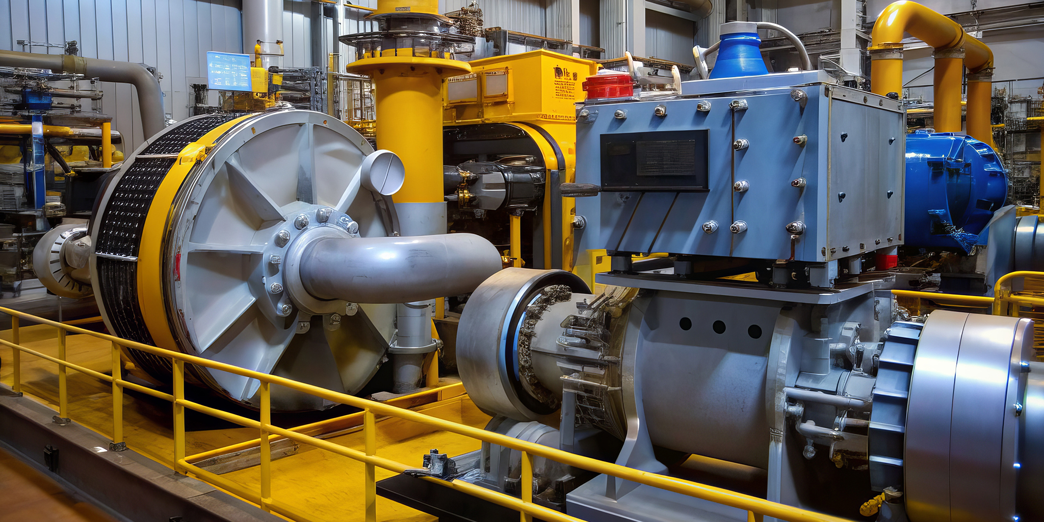
Reciprocating compressors are widely used across the oil, gas, petrochemical and process industries due to their ability to handle high pressures and variable operating conditions. However, these machines introduce a challenge that must be addressed carefully at the design stage: vibration in the connected piping system.
Unlike rotating equipment, reciprocating compressors generate cyclic pressure fluctuations as pistons move back and forth within the cylinders. These fluctuations are transmitted directly into the suction and discharge piping, creating pressure pulsations that travel through the system. If these pulsations are not properly controlled, they can excite acoustic resonance within the piping, leading to excessive vibration, fatigue damage, support failures and, in extreme cases, loss of containment.
This article explains how vibration issues arise in piping systems connected to reciprocating compressors and outlines a structured engineering approach to prevent them. The focus is on acoustic and pulsation‑induced vibration, in line with API 618 and ASME B31.3, rather than mechanical issues such as imbalance or misalignment.
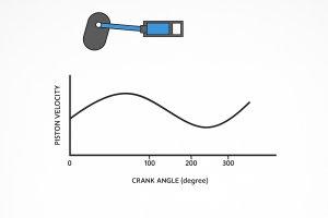
Figure 1: Sine wave created due to continuous to and fro motion of slider crank mechanism.
Why piping vibration occurs
Reciprocating compressors are positive displacement machines. Every piston stroke generates a pressure wave that propagates through the connected piping. The piping system itself behaves like an acoustic circuit, with natural frequencies determined by its geometry, fluid properties and boundary conditions.
When the frequency of pressure excitation from the compressor aligns with one of the piping system’s natural acoustic frequencies, resonance occurs. Under resonance conditions, even small pressure oscillations can be amplified significantly, resulting in large dynamic forces and vibration amplitudes.
These vibrations are not limited to the compressor nozzle. They can extend across long pipe runs, affect supports and structures, and induce fatigue damage at elbows, tees, reducers and small bore connections. This is why vibration control must be considered as a system‑level problem, not a local one.
Scope of vibration and pulsation studies
The vibration issues discussed here arise specifically from acoustic effects generated by reciprocating compressors. Mechanical vibration sources such as rotating imbalance, coupling misalignment, foundation defects or lubrication problems are outside the scope of this discussion.
Because the compressor is the primary source of pulsation, its interaction with the connected piping must be evaluated under operating, transient and shutdown conditions. Acoustic modelling and pulsation studies are therefore essential inputs to piping layout, support design and overall system configuration.
What analyses are required
API 618, 8th Edition, Clause 7.9.4.2 defines the scope of pulsation and vibration studies for reciprocating compressors. These studies typically include three complementary components.
Static piping stress analysis
A static piping stress analysis, often referred to as equivalent static analysis, is performed for the discharge piping between the compressor and downstream equipment such as intercoolers or aftercoolers. Other connected lines, including pressure safety valve headers and bypass lines, are also included where they fall within the critical scope.
The analysis boundary should terminate at a well‑defined anchor with stiffness significantly higher than adjacent supports, or sufficiently far from the compressor so that boundary effects do not influence the results. The objective is to ensure stresses, displacements and support reactions remain within allowable limits under operating and dynamic conditions.
Dynamic and pulsation analysis
Dynamic analysis focuses on the pressure pulsations generated by the compressor and their impact on the piping system. API 618 defines three design approaches.
- Design Approach 1 (DA‑1) focuses on empirical sizing of pulsation suppression devices such as bottles or dampeners with its internal configuration like baffles, choke tubes. The objective is to minimize pulsation amplitudes within acceptable API limits and optimize the acoustic performance of the system.
- Design Approach 2 (DA‑2) involves detailed acoustic analysis to predict pressure pulsations, peak‑to‑peak amplitudes and shaking forces. This ensures that pulsation levels remain within acceptable limits to prevent process and mechanical issues.
- Design Approach 3 (DA‑3) : The DA3 (Detailed Acoustic Analysis, Level 3) approach includes analytical equations and modelling techniques to accurately predict the pressure drop and acoustic behaviour of the system. These equations account for flow resistance, pulsation effects, and energy dissipation within the piping network apart from addressing mechanical vibration behaviour, ensuring acceptable separation between excitation frequencies and system natural frequencies.
Small bore connection assessment
Small bore connections, typically 2-inch nominal pipe size and below, are particularly vulnerable to vibration‑induced fatigue. Instrument take‑offs, drains, vents, relief lines and PSV branches must be assessed individually for likelihood of failure based on geometry, mass, support adequacy and proximity to high‑vibration zones.
Equivalent static piping stress analysis
Static stress analysis of piping connected to reciprocating compressors is carried out in accordance with ASME B31.3 using recognised tools such as CAESAR II.
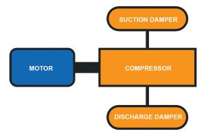
Figure 2: Schematic model of compressor skid.
The piping system and connected equipment are modelled with all relevant parameters, including material properties, pipe sizes, insulation, weights, supports, gaps, friction and anchor stiffness. Modal analysis is included for compressor‑connected piping, with a minimum target natural frequency of 4.5 Hz as common industry practice.
Accurate modelling of boundary conditions is critical. Using overly rigid anchors where none exist can lead to unrealistic and overly conservative results. Supports, gaps and friction must reflect actual site conditions.
Support configuration, clamp behaviour and stiffness modelling
Support design plays a decisive role in controlling vibration in piping systems connected to reciprocating compressors. While conventional resting or guided supports may be adequate for static loads, they are often insufficient where pressure pulsations introduce cyclic dynamic forces.
In such cases, clamp‑type supports are widely used to increase local stiffness and restrict excessive movement. By gripping the pipe and transferring loads more directly to the supporting structure, clamp supports help raise the mechanical natural frequency of the system and reduce vibration amplitudes.
However, clamp supports must be applied with care. Increasing stiffness at one location alters load paths and can influence thermal stresses and nozzle loads elsewhere in the system. For this reason, clamp supports are always evaluated as part of the overall stress and vibration analysis rather than added as a construction‑stage fix.
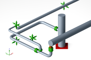
Figure 3: Caesar II model with clamp support
In analytical models, clamp supports are represented using realistic stiffness values rather than idealised rigid restraints. The overall support stiffness is governed by the combined effect of the clamp stiffness and the stiffness of the supporting structure. This relationship is expressed as:
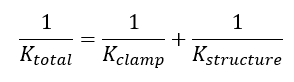
Where:
- K total is the effective stiffness of the support
- K clamp is the stiffness of the clamp provided by the manufacturer
- K structure is the stiffness of the supporting steel or foundation
Incorporating this combined stiffness ensures that both static stresses and dynamic response are captured realistically in the analysis. This is particularly important for highly constrained piping systems and for piping connected to reciprocating compressors, where accurate load transfer directly affects vibration behaviour.
Where clamp supports are introduced, their impact on thermal expansion, support reactions and equipment nozzle loads is always reviewed to avoid over‑constraining the system. Achieving the right balance between stiffness and flexibility is central to vibration‑resistant piping design.
Stress limits and code compliance
Static stress analysis differentiates between primary, secondary and occasional stresses.
- Primary stress, induced by weight and pressure, must satisfy:

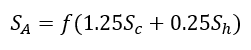
- Secondary stress, caused by thermal expansion, must satisfy:
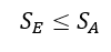
where:
- Occasional stress, due to wind or seismic loads, must satisfy:
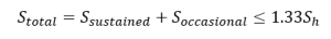
All stresses are evaluated in accordance with ASME B31.3 requirements.
Load Cases
All relevant operating and design load cases shall be considered in the stress analysis, including but not limited to:
- Operating cases (rated, start-up, purge, shutdown) as specified in the datasheet.
- Environmental loads such as seismic and wind.
- Thermal extremes, including cryogenic or high-temperature conditions.
Support selection and configuration
- Minimize static stress, nozzle loads and displacements while meeting vibration control needs.
- Use resting, guides, and hangers to control loads and thermal movements where appropriate.
- For piping subjects to vibration, consider more restrictive supports (hold-downs, clamps) to limit dynamic movement API-618 guidance discourages simple rest/guide/hanger-only solutions where vibration is significant.
- Clamp supports increase local stiffness and help in reducing vibration; evaluate thermal restraint and resulting stresses when clamps are used.
Modal analysis and frequency separation
Modal analysis is essential for piping connected to reciprocating compressors. The objective is to ensure that the mechanical natural frequency of the piping system is sufficiently separated from the compressor excitation frequency.
Industry practice targets a minimum natural frequency of 4.5 Hz, with higher values preferred. If modal results indicate frequencies close to excitation harmonics, mitigation measures such as routing changes, added stiffness, additional supports or dampeners must be considered.
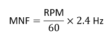
API 618 requires a minimum separation margin of 20 percent between the mechanical natural frequency and the excitation frequency. For reciprocating compressors, excitation frequency is typically calculated as:
Pulsation and shaking force evaluation
Pulsation analysis is performed using specialised software such as PULSIM, following API 618, 5th Edition requirements. The simulation model includes the complete compressor circuit between upstream and downstream large‑volume equipment.
Key outputs include pressure pulsation levels, shaking forces, pressure drop, vibration criteria and cyclic stress.
Shaking forces originate at discontinuities in the piping system such as elbows, tees, and reducers, due to abrupt changes in flow direction or area. Excessive shaking forces may lead to increased vibration and fatigue failures.
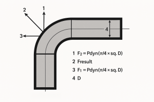
Figure 4: Shaking forces at elbows.
Allowable shaking forces are defined in API 618. For example:
- For cylinder‑mounted suppression devices:
- For piping systems:
If calculated shaking forces exceed allowable limits, system modifications such as acoustic tuning, support stiffening or addition of pulsation control devices are required.
Pressure drop and vibration limits
API 618 limits total pressure drop in the piping system to 0.25 percent of line pressure under rated conditions, ensuring process efficiency.
Permissible constant vibration velocity for design evaluation is approximately 32 mm/s peak‑to‑peak. For piping systems operating below 370 °C, the maximum allowable cyclic stress range is 180 N/mm².
Small bore piping connections
Small bore piping is particularly susceptible to vibration. Recommended practices include:
- Using SCH 80 or higher thickness
- Avoiding threaded fittings near vibration‑prone areas
- Preferring weldolets and sweepolets
- Locating heavy items close to supports
- Minimising unsupported spans
Support stiffness should be increased through bracing and gussets, while spring supports should generally be avoided.
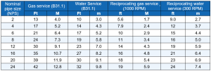
Recommended support span table
Mitigation and best practices
Effective vibration control relies on an integrated approach:
- Independent modal analysis of suction and discharge piping
- Increasing piping natural frequency by reducing support spans
- Avoiding small bore connections near turbulence sources
- Strengthening supports and structural elements
- Using pulsation suppression devices where required
- Adopting sound routing and layout practices
- Use clamped type support with rubber pad between pipe and clamp
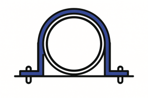
Figure 5:Recommended Anti vibration Clamp type support
Conclusion
Vibration in piping systems connected to reciprocating compressors is a well‑known but manageable engineering challenge. By combining static stress analysis, pulsation modelling, modal analysis and disciplined support design, vibration‑related failures can be effectively avoided.
A well‑designed piping system not only meets ASME B31.3 and API 618 requirements but also delivers long‑term reliability, reduced maintenance and safer plant operation. When vibration control is addressed early and systematically, the benefits extend well beyond compliance to overall operational excellence.


